
Description
The definition of pipeline mechanical pig indicator

Technical characteristics:
Operating pressure: 0-5/5-10MPa
Operating temperature: -20~120℃
Installation pipe diameter: ≥89mm
Transport medium: non-corrosive fluid
Applicable dangerous places: Zone 1 and Zone 2
Suitable for explosive gas mixture: IIA, IB, ⅡIC.
Riot sign: Exd IIBT4
Protection level: IP65, IP66
Corrosion protection grade: WF1
Remote contact capacity: 24V DC 3A
Remote transmission interface: 1/2NPT,
Product features:
The product is the basic type of minimum composition and can work independently to complete the basic function of the ball indication.
Product work, built-in timer, automatic travel, can display the standard time (intelligent control, digital display), memory times: 20.
The supply voltage of this product is DC6V.
Scope of application:
Places of explosive gas and flammable media.
Explosion-proof mark dII BT4

How to use:
Unscrew the battery compartment cover, put in two CR123A batteries according to the polarity shown in the figure, and then tighten the battery compartment cover.
Turn on the power switch on the panel and display the current timing time in the display window. If it needs to be adjusted, press the “Set” key on the front panel and the number to be adjusted will start to blink. Press the “Set” key continuously and the blinking number will shift to the right. Press the “Adjust Time” key to adjust the time. After completion, press the “Set” key to the end of the last digit (no, there is a blinking number).
One minute later, the clock display automatically turns off and the energy-saving indicator starts to blink, indicating that the device has entered the energy-saving mode in the test state.
Note: If you enter the energy-saving state during the adjustment, press “Display” to restore the display.
If you need to observe the time or adjust it during the working process, press the “Display” key and the clock display will light up. One minute later, the clock display automatically turns off, the energy-saving indicator starts to blink, and the device enters the energy-saving mode in the test state again.
Enter the test state:
In the test state, when the clock is accurate, (press the “Display” key to display the current time), when the pig passes, the clock display will light up and stop traveling, and the pig’s passing time will be displayed. This state will remain until the end of power off.
To restart:
Turn on the power switch again and the device will enter the test state again.
The mechanical part resets automatically.
Matters needing attention
The polarity of the power supply cannot be reversed.
Do not hit the display window with heavy objects during installation.
Replace the battery before use.
Be sure to remove the battery at the end of use.
Technical characteristics of mechanical transmission:
Design pressure: 15MPa.
Operating temperature: -20-120℃.
Installation pipe diameter>89mm.
Transport medium: oil, water, natural gas, and other non-corrosive fluids.
Pipeline material:
A: Steel of all kinds of metals with good weldability.
B: Stainless steel for special environmental requirements.
The length of the plate machine into the tube is more than 15mm.
This indicator can display normally when the pipeline passes through the pig in both directions.
Suitable for installation in explosion-proof places.
The clock control indicator adopts the electronic clock core body. When the swing of the board is greater than 45 degrees, the clock stops to display the time of the pig passing.
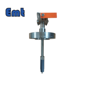
Basic structure:
In basic structure (see the attached figure), the indicator is mainly composed of a mechanical body and display mechanism (clock control head or sign indication, explosion-proof digital display, etc., and can be customized according to user needs into electricity, light, sound signal source, and remote transmission function).
Plate machine: two-way rotation.
Wire plug: referring to the standard 2″ wire plug system, meet the installation conditions with pressure.
Base: carbon steel, alloy steel, or 304 stainless steel with good welding performance.
Sealing ring.
Tappet.
The spring.
Stop washer (stop screw).
Grow stud tappets.
Pole system.
Tighten the screws.
The inner contact rod: push it, can make the clock control head stop; Can make the mechanical indication sign to stand up, digital display through time and remote transmission.
Display mechanism: according to user needs can be installed clock control head, and mechanical indicating mechanism explosion-proof digital display or electricity, light, and sound signal source.

Installation method:
Before installation, check that the mechanical body of the indicator and the display mechanism are flexible and reliable, disassemble the mechanical body according to the structure and installation diagram, and weld the base and pipeline separately.
Welding base:
Pressure-free installation: Clean the installation position, remove all attachments, reveal the metal color, and straighten the base (welding azimuthal diagram), so that the grooving direction of the upper end of the base is parallel to the center line of the pipeline or the mark of the upper end of the base is in the center line of the pipeline (the grooving direction of the base or the mark is consistent with the movement direction of the plate machine). Press the base to prevent displacement or deflection during welding.
Pipeline mechanical pig indicator


Reviews
There are no reviews yet.