
Description
Summary
Working principle
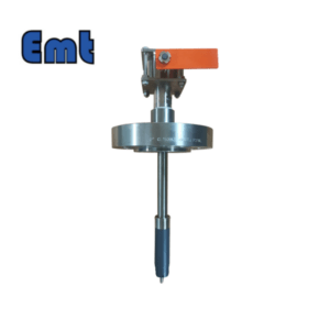
The firing pin that can be triggered bi-directionally is installed at the end of the extension sleeve and inserted into the pipe near the pipe wall through the nozzle of DN50. When the pig passes through, the firing pin is moved, and the action is transmitted to the instrument button through the connecting rod in the sealing bushing, triggering the display instrument to work.
The display instrument is a real-time time display and recording system. The action produced by the firing pin triggers the instrument to work and realize the parameter recording. The operation button can also trigger the meter to realize parameter readings and battery tests.
Appearance of instrument
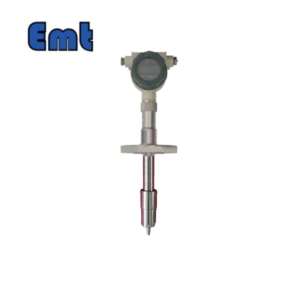
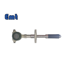
The instrument consists of a body and a display instrument, which are connected with knurled nuts.
There are two indicators on the instrument panel. Hit is the impact indicator, indicating the main action, and T&R is the test and reset indicator, indicating the button action.

Working mode
1. Pig through the trigger
After the pig is triggered, the number of pass balls is increased by 1. The number of pass balls and cumulative time values are displayed upward, and the current time is displayed downward. It shuts down automatically after 2 hours,
2. Push button trigger
At any time, press the button on the side of the meter to trigger an upward display of the exact date of the last pig pass, such as 06/02/15 or February 15, 2006. Downlink display time to pass, such as 13:35:42 namely 13:35 minutes 42 seconds, after a delay of a period of time display battery detection results, give a prompt in both Chinese and English after automatic shutdown (battery is insufficient, through the trigger, after completing the count and record the passing time immediately automatic shutdown, in order to save energy);
Selection
1. Connecting flange: 2 “ANSI 600# RF flange; User specified
2. Probing length (distance between the top flange and the inner wall of pipe): 80mm; 150mm; Custom made.

Main technical indicators
1. Working pressure: 4.0MPa; 6.4 MPa. 10MPa;
2. Power supply: AA1.5V alkaline battery 4;
3. Working hours: ≥10 hours;
4Recording and display mode:
After the pig is triggered, the number of pass balls is increased by 1. After 2 hours of timing, it will automatically shut down. The number of pass balls and cumulative time value will be displayed upward, and the current time will be displayed downward;
At any time, press the button on the side of the instrument to trigger an upward display of the exact date of the last pig passing, such as 06/02/15, i.e., February 15, 2006. Downlink display time to pass, such as 13:35:42 namely 13:35 minutes 42 seconds, after a delay of a period of time display battery detection results, give a prompt in both Chinese and English after automatic shutdown (battery is insufficient, through the trigger, after completing the count and record the passing time immediately automatic shutdown, in order to save energy); OOCIST
5. Installation: ANSI 600# RF flange connection above pipe (standard);
6. Installation requirements: The distance between the upper surface of the mounting flange on the pipeline and the inner wall of the pipeline is the probe length of 2mm in the selection: (according to the requirements of the user in the safety dimension of the ball indicator manufactured by the user).
7.Ambient temperature: -20~~75° C:
8. Far transmission out type electrical parameters::1/2NPT;
Switch type: solid state relay or SPDT/DPDT mechanical relay
Switching capacity: 2A/24VDC

Installation method
Flanges (flange specification, grade, mounting hole distribution, etc., shall be in accordance with ANSI 16.5 or Custom standards) shall be pre-installed on the piping prior to installation of the ball-through indicator. Choose a sealing gasket with a thickness of less than 4mm, between the two flanges (RJ sealing surface is selected according to the standard requ
The display instrument is connected to the main body through knurled nuts. When the battery needs to be replaced, open the knurled nut connection. Move the display instrument to a safe place, open the back cover of the instrument, remove the battery compartment, and replace the battery. After changing the battery, the instrument should be in the but-open state (indicating that the instrument is in a forced startup state when it is out of the main body). If it is not started, it is because the battery compartment is tight and a positive electrode of the battery does not touch the contact point.
The display instrument has only one operation button, which is used to read the last ball time and check the battery condition of the instrument. It is used to read the time of the last passing ball. If the battery is insufficient, it must be replaced in time. If the battery is OK, it means that the power supply is sufficient to complete parameter recording and can not be replaced temporarily.
The meter’s real-time clock is not adjustable and the time error is not more than 2 minutes/year.
increments), the direction of the instrument firing pin is directed towards the direction of the pipeline (that is, the gap is aligned with the direction of the pipeline), insert the extension sleeve into the pipeline, and tighten it with bolts.
Teletransmission function and usage
SN2-TQZ explosive digital display through the ball indicator can be attached to a remote transmission module for remote control or display. The output signal is ON/OFF switching quantity (DC3~24V/ 2A electronic switch, 2A is the maximum current allowed through the electronic switch). The control circuit for the output signal is provided by the internal 6V power supply. When the display instrument is working, the electronic switch is on (on). Press the button on the side of the instrument. After a few seconds, the remote transmission module will be reset and closed when the display part automatically closes.
When the output electronic switch is on for a long time, the load resistance should be greater than 30 ohms. Or make its working current less than 1A.
Reviews
There are no reviews yet.